BL6a
Structure of BL-6 beamline
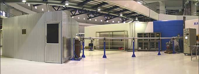
BL-6 beamline provides synchrotron light in low energy X-ray range to users who study X-ray exposure on materials or who use X-ray in lithography of ultrathick photoresists to fabricate high-aspect-ratio microstructures. Synchrotron light from BL-6 beamline is generated from bending path of high energry traveling electrons inside strong magnetic field of BM-6 electromagnet and is transported through filters to the exposure station at the end of beamline. Three considerations have been taken into account in construction of the beamline:
1. Separation between high-pressure exposure chamber in range of 10-2 - 10-4 torr from front-end beamline and electron orbit ring, which are in ultra-high vacuum of 10-9 - 10-11 torr range, is needed. Be window and interlocking pneumatic valves are used for this purpose.
2. Since electron bending in strong magnetic field of BM-6 magnet is broad band, filters are needed to screen out synchrotron light with unwanted wavelengths. Be windows and other materials such as aluminum and polyimide sheets are used as filters so that only synchrotron light in low-energy X-ray range passes out to exposure chamber.
3. By nature, synchrotron beam is horizontally flat and eliptic. Vertical scanning mechanism is required in order to expose the light on a sample of large area.
The structure of BL-6 beamline is divided into three stages, the front-end part, experimental hall part, and the sample scanner.
Front-end
Ultra-high vacuum line used to transport synchrotron light from electron orbit ring to the experimental hall. This part has an ultra-high vacuum of 10-9 - 10-11 torr, the same level as that of the orbit ring. Key components in this part include photon mask 1, heat absorber, ion pump, photon mask 2, and beam shutter.
Beamline in the experimental hall
This part of the beamline is separtated from the front-end part by a 100 microns-thick Be window and is in a vacuum of 10-2 - 10-4 torr. The Be window also screen out synchrotron light with wavelength greater than 1.24 nm.
Sample scanner
The sample located in exposure chamber is veritcally scanned so that it passes throught a horizontal line of X-ray beam which has passed through the Be window filter. Amount of photon energy required to expose on a sample can be calculated using parameters such as electron current in the orbit ring, thickness and type of filters, photon absorption of the sample and scanning velocity.
Fig. 1 and 2 show photographs of components in front-end beamline and the part located in the experimental hall. Fig. 3 shows a photograph of equipments inside the exposure station. This station is illuminated by yellow light to prevent the sample from exposing to white light. Locations and functions of beamline components are summarized in Table 1 and technical specifications of the beamline are shown in Table 2. Fig. 4 shows a typical photon spectrum output obtained from the BL-6 beamline through various filters.
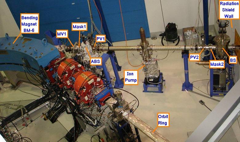
Fig. 1Front-end of BL-6 beamline (inside radiation shiled wall)
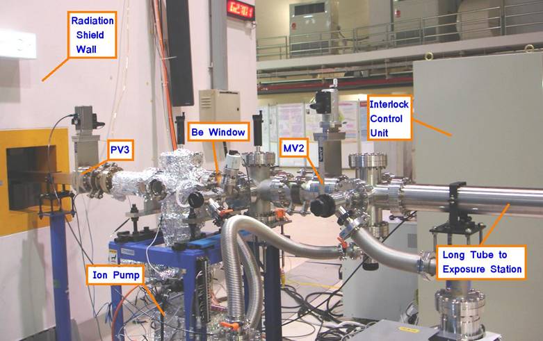
Fig. 2BL-6 beamline in the experimental hall
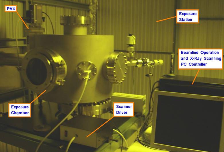
Fig. 3Equipments in exposure station
Table 1 Details of BL-6 beamline components
|
Component |
Location |
Function |
|
Bending Magnet (BM-6) |
Inserted in Obit Ring |
Forces electrons to travel in curved path so that they emit broad-band synchrotron light. |
|
Manual Valve 1 (MV1) |
Between BM-6 and Mask1 |
Separates the Orbit Ring from BL-6 beamline at maintenance time. MV1 is usually opened. |
|
Photon Mask 1 (Mask1) |
Between MV1 and ABS |
Primarily defines the size of synchrotron light beam emitted from the BM-6 magnet so that no part of the beam hit the transport tube. |
|
Heat Absorber (ABS) |
Between Mask1 and PV1 |
Shuts off the synchrotron light beam by with thick slab of lead absorber. The heat generated in the process is removed by continuous water cooling. |
|
Pneumatic Valve 1 (PV1) |
Between ABS and first Ion Pump |
Separates the vacuum of the orbit ring from that of the front-end beamline. |
|
First Ion Pump |
Between PV1 and PV2 |
Creates ultra-high vacuum in a range of 10-9 - 10-11 torr inside the front-end beamline. |
|
Pneumatic Valve 2 (PV2) |
Between Ion Pump and Mask2 |
Limits the length of vacuum tube maintained by the first Ion pump. |
|
Photon Mask 2 (Mask2) |
Between PV2 and BS |
Defines the size of photon beam so that no part of it hits the wall of consecutive transport line. |
|
Beam Shutter (BS) |
Between Mask2 and Radiation Shield Wall |
Shields harmful secondary radiation generated from Heat Absorber. |
|
Radiation Shield Wall |
Between BS and PV3 |
Shields harmful radiation generated from the Orbit Ring, BM-6 bending magnet and front-end beamline. |
|
Pneumatic Valve 3 (PV3) |
Between Radiation Shield Wall and second Ion Pump |
Separates front-end beamline from the portion in the experimental hall. |
|
Second Ion Pump |
Between PV3 and Be Window |
Creates ultra-high vacuum in a range of 10-9 - 10-11 torr inside the beamline portion between PV3 and Be Window. |
|
Be Window |
Between second Ion Pump and MV2 |
Separates the low vacuum (exposure station side) from the ultra-high vacuum (storage ring side) portions of the beamline. It also filter out synchrotron light whose wavelength is greater than 1.24 nm so that the sample in end station is exposed to low-energy X-ray photons. |
|
Manual Valve 2 (MV2) |
Between Be Window and Long Tube |
Separates Long Tube from Be Window at maintenance time. MV2 is usually opened. |
|
Long Tube |
Between MV2 and PV4 |
Extends the source-to-sample distance to obtain larger incident area of photon beam on the sample. X-ray exposure onto a sample is done in vacuum of 10-2 - 10-4 torr. |
|
Interlock Control Rack |
Near Be Window |
Controls the vacuum valve system to prevent serious damages from air leakage into the Orbit Ring. All vacuum valves in the beamline will be automatically closed immediately if abnormal pressure is detected inside the beamline. The unit is based on PLC (programable logic controller). |
|
Exposure Station |
End of Long Tube |
Serves as a housing of the exposure chamber in which atmospheric cleanliness is controlled by compressing air into the staion through a HEPA filter so that air pressure inside this room is slightly higher than outside. Since SU-8 photoresist used in X-ray lithography processes is sensitive to white light, the exposure station is set under yellow lighting. |
|
Pneumatic Valve 4 (PV4) |
End of Long Tube inside Exposure Station |
Separates Long Tube from exposure chamber. This valve is closed before the exposure chamber is vent and opened for sample exchange. After sample installation, pumping time of exposure chamber is greatly reduced sicne the Long Tube was kept under vacuum during sample exchange procedure. The valve is opened only after the pressure of exposure chamber is lower than that of Long Tube. |
|
Exposure Chamber |
End of beamline next to PV4 |
Houses the sample and its scanner. |
|
X-Ray Scanner |
Inside Exposure Chamber |
Drives the sample so that it passes up and down through a horizontal line of X-ray beam. Scanning sample vertically is used to obtain larger exposured area on the sample. Scanning duration depends on beam intensity and desired exposure dose. |
|
Exposure Control PC |
Near Exposure Chamber |
Drives the X-ray scanner, remotely controls the Interlock Control Rack through RS-232 communication, as well as records exposure data. |
Technical specifications
Table 2Summary of BL-6 beamline's parameters
|
Electron energy |
1.2 GeV |
|
Bending magnet radius |
2.78 m |
|
Bending magnet field strength |
1.44 T |
|
Natural emittance |
41 nm.rad |
|
Critical photon energy |
1.38 keV |
|
Gaussian width at 10-degree port |
H: 320 microns V: 47 microns |
|
Opening angle of 100 micron-thick Be window |
H: 5.3 mrad V: 1.1 mrad |
|
Transmitted band-pass spectrum |
2 keV - 8 keV |
|
Source-to-sample distance |
17.44 m |
|
Beam size at sample |
H: 87.2 mm V: 7.4 mm |
|
Vertical scanning length of sample |
100 mm |
|
Opening diameter of circular sample holder |
80 mm |
|
Scanning speed |
0.8 mm/s |
|
Time duration in which a point on the sample passes through the beam height |
9.25 s |
|
Time duration in which the sample travels for 1 cm |
0.21 minutes |
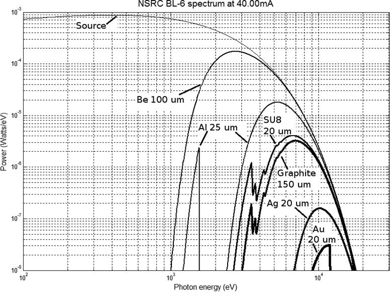
Fig. 4Synchrotron light spectrum from BL-6 beamline after various filters


111 SirinthonWitchothai Building, University Avenue, Muang District, Nakhon Ratchasima 30000, THAILAND
Tel.: +66 44 217 040 Fax: +66 44 217 047 Email: siampl@slri.or.th
Copyright © 2015 Synchrotron light research institute. All Rights Reserved.
|
|