
Beamline 1.2W
X-ray Tomographic Microscopy
BL1.2W: X-ray Tomographic Microscopy (XTM)
Synchrotron Light Research Institute (SLRI), Thailand
The XTM beamline provides synchrotron X-ray micro-computed tomography (SR-MicroCT) for non-destructive 3D visualization of the internal structure of samples. Using an intense polychromatic beam from a 2.2 T multipole wiggler on the 1.2 GeV storage ring, the beamline delivers lower noise and higher spatial resolution (down to 1.5 µm) than conventional laboratory X-ray tube micro-CT.
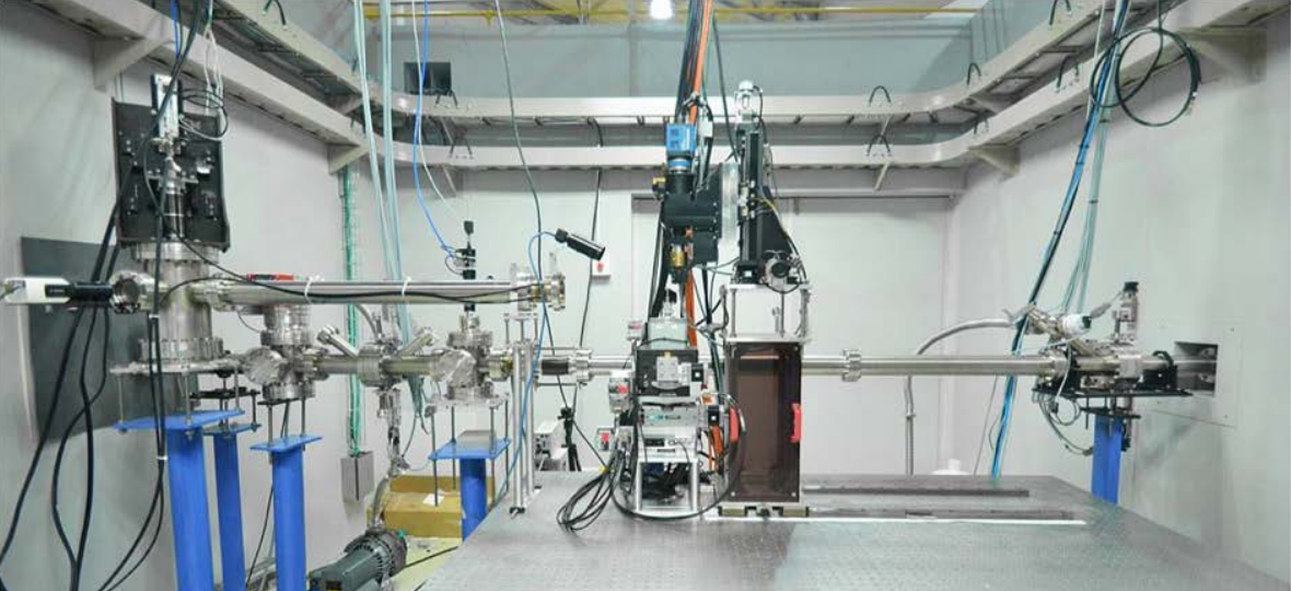
Specifications
| Source | Multipole wiggler, 2.2 T |
|---|---|
| Storage ring | 1.2 GeV |
| Radiation type | Polychromatic (white) beam |
| Energy range | 5 – 20 keV |
| Beam size | 10 × 4 mm (H × V) |
| Imaging efficiency | 100 frames/s |
| Spatial resolution | 1.5 µm (pixel size 0.72 µm) |
| Projection microscope | Optique Peter white-beam microscope, 2×, 5×, 10× |
| Detector | YAG:Ce scintillator + sCMOS camera (PCO.edge 5.5) |
| Data acquisition / analysis | LabVIEW-based: XIMaq, XIMove; Octopus |
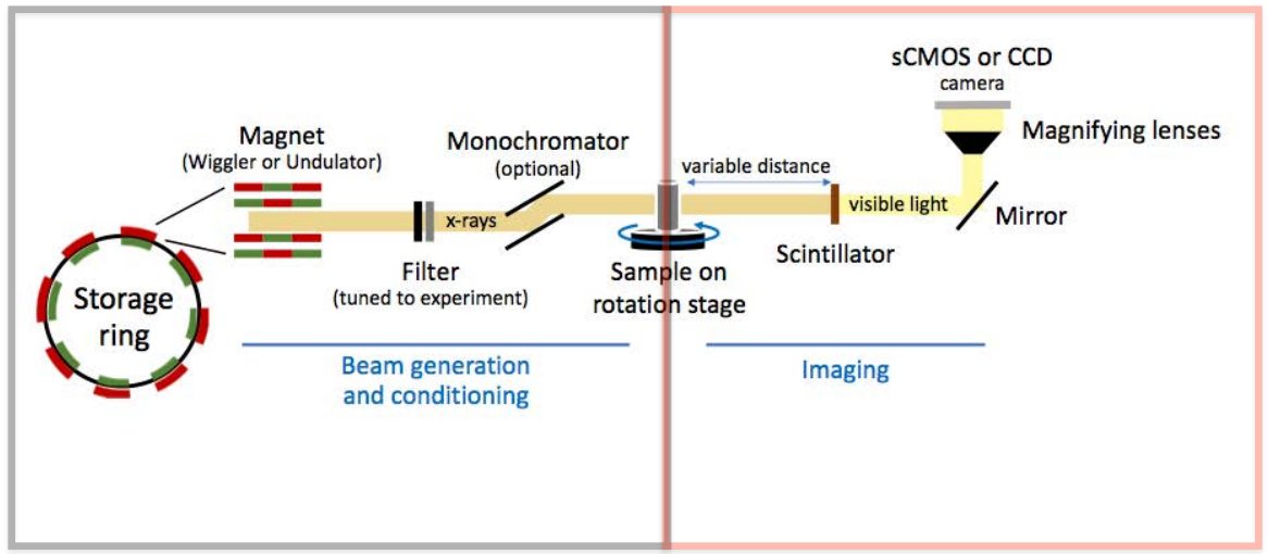
Beamline Layout
- Multipole wiggler
- WB slits
- Toroidal focusing mirror
- Be window
- Attenuator
- Rotating sample
- Scintillator
- Microscope
- sCMOS camera
Optical Performance
PCO.edge sCMOS camera (2560 × 2160 pixels)
| Magnification | 2× | 5× | 10× |
|---|---|---|---|
| Horizontal field of view (mm) | 9.24 | 2.47 | 1.85 |
| Vertical field of view (mm) | 7.80 | 2.08 | 1.56 |
| Pixel size (µm) | 3.61 | 0.96 | 0.72 |
| Depth of focus, ± (µm) | 146 | 8.5 | 4.8 |
| Max. resolution (µm) | 5 | 3 | 1.5 |
Facilities
Experimental hutch
CT station with rotating sample stage, white-beam microscope and sCMOS detector.
Control cabin
Experiment control and setup, data acquisition, sample preparation, data processing and backup.
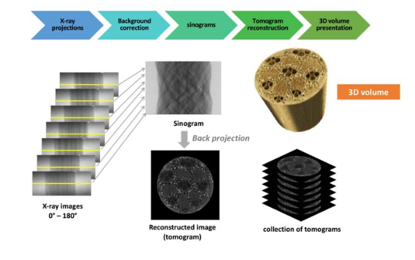
How It Works
Applications
Medical science
Bone porosity analysis (e.g. osteoporosis studies), 3D surface rendering of bone.
Agricultural science
Soil structure, e.g. biochar-amended soil; insects such as bagworms and beetles.
Earth science
Microfossils (<500 µm) such as foraminifera and ostracods, fossil skulls, gemstones.
Material science
Phase distribution in cement and composites (BaTiO₃/PDMS), corrosion propagation in stainless steel welds.
Development Timeline
- 2015 Front end, optics and hutch
- 2016 Interlock system, experimental hutch, first X-ray image
- 2017 CT station, XIMaq 1, first 3D CT, commissioning
- 2018 User operation in white-beam mode, XIMaq 3, serial scan
- 2019 Monochromatic beam mode, rapid data acquisition (planned)