Experimental-station
experimental-station
Experimental Station
The primary advantage of the TRXAS end-station is its ability to record complete X-ray absorption spectra simultaneously and rapidly. This makes it an ideal tool for in-situ measurements to monitor structural and electronic changes in samples under various environmental conditions, such as high temperature, pressure, or specific gas atmospheres.
In-situ Environmental System
Currently, the institute provides a specialized Heating Cell designed to support a wide range of in-situ research applications, enabling simultaneous temperature control and atmospheric regulation.
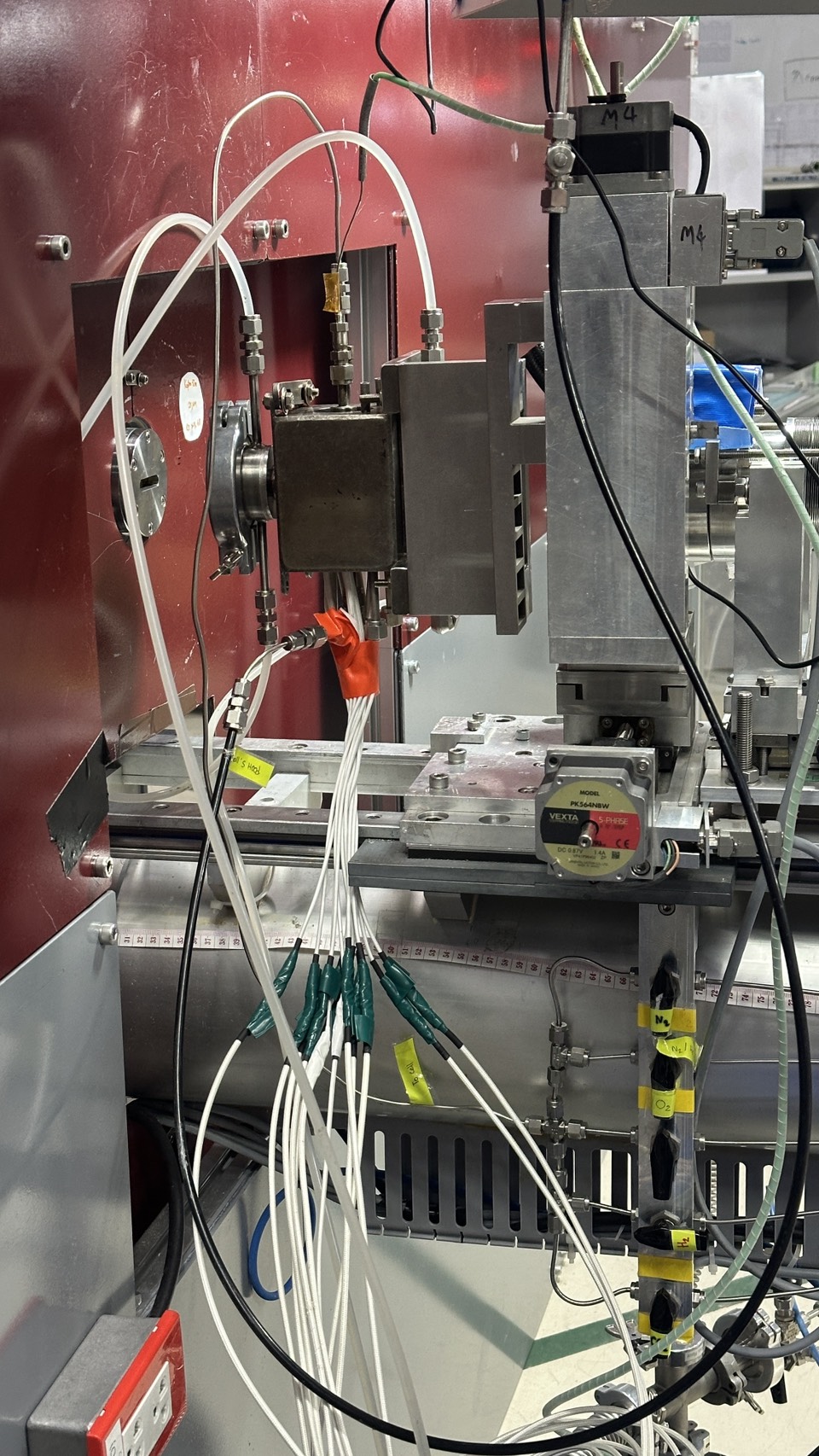
| Material | Stainless Steel Body |
|---|---|
| Body Dimensions | 45 × 45 × 70 mm |
| Sample Holder | 16 mm diameter (pre-drilled hole) |
| Windows | Dual Kapton windows with water cooling system |
| Heating Source | 6× Cartridge Heaters (8 mm OD, 250 W each) |
| Maximum Operating Temperature | 973 K (700 °C) |
|---|---|
| Ramp Rate | 5–20 °C/min |
| Controller | Eurotherm 2216e with K-type thermocouple |
| Stability | ± 0.1 K |
The cell is designed to accommodate various gas environments for catalytic and material study.
| Available Gases | N2, O2, He, Ar, CO2 and H2 |
|---|---|
| Flow Control | AALBORG Mass Flow Controllers (MFCs) |
| Flow Rate / Ranges | 0–100 sccm and 0–25 sccm |
In-situ Battery System
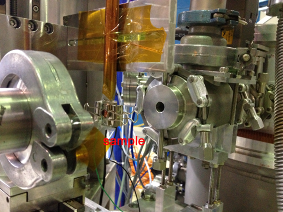
The cell structure consisted of a cap, anode, separator, cathode, spring, and case. The coin cell (CR2032) with an OD of 20 mm was used. To assemble the cell, an anode (Li foil, 0.75 mm thickness), separator (Celgard 2400, 25 μm thickness), cathode (LFP) and spring (stainless steel, 0.3 mm thickness) were provided. Since the case and cap were made from stainless steel, they did not allow X-ray transmission. Thus, an aperture with OD 8 mm sealed with Kapton film was provided.
Coin Cell Analyzer 5V10mA Battery Testing System
| AC Input | AC 220V ±10% 50Hz |
|---|---|
| Power | 25 W |
| Resolution | AD: 16 bit; DA: 12 bit |
| Input | ≥ 1 MΩ |
| Category | Parameter | Specification |
|---|---|---|
| Voltage | Measuring Range | Charge: 25 mV – 5 V Discharge: 25 mV – 5 V |
| Discharge Min Voltage | 0 V | |
| Accuracy | ± 0.1% of FS | |
| Stability | ± 0.1% of FS | |
| Current | Range | Charge: 0.05 – 10 mA Discharge: 0.05 – 10 mA |
| Accuracy | ± 0.1% of FS | |
| Stability | ± 0.1% of FS | |
| Power | Output Power Per Channel | 0.05 W |
| Stability | ± 0.2% of FS | |
| Time | Rise Time | 1 ms (0 ~ Full Range) |
| Step Time | ≤ (365×24) hour/step Time format 00:00:00 (h:min:s) | |
| Data Acquisition | Intervals | Δt: 1 – 60000 s ΔU: 10 mV – 5 V ΔI: 0.02 – 10 mA |
| Frequency | 1 Hz | |
| Charge | Mode of Operation | CCC, CVC, CC & CVC |
| End Conditions | Voltage, Current, Test Time, Capacity | |
| Discharge | Mode of Operation | CCD, CPD |
| End Conditions | Voltage, Current, Test Time, Capacity | |
| Cycle | Cycles | 65535 |
| Steps | 63 | |
| Nested Function | Max three levels of loops |
Detector System
To measure XAS spectrum, the position sensitive detector (PSD) is used.
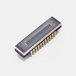
S3904-1024F — NMOS Linear Image Sensor with Scintillator (Hamamatsu Photonics K.K.)
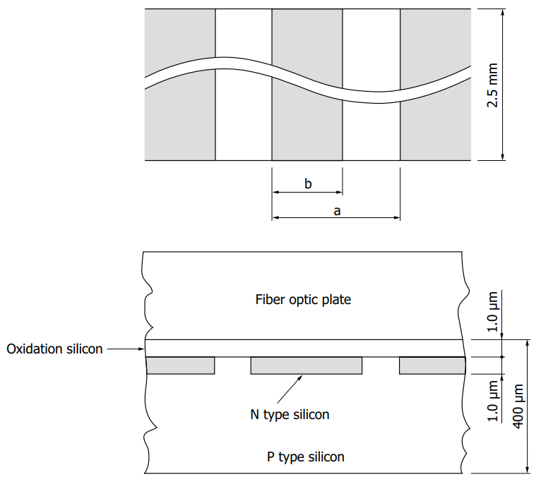
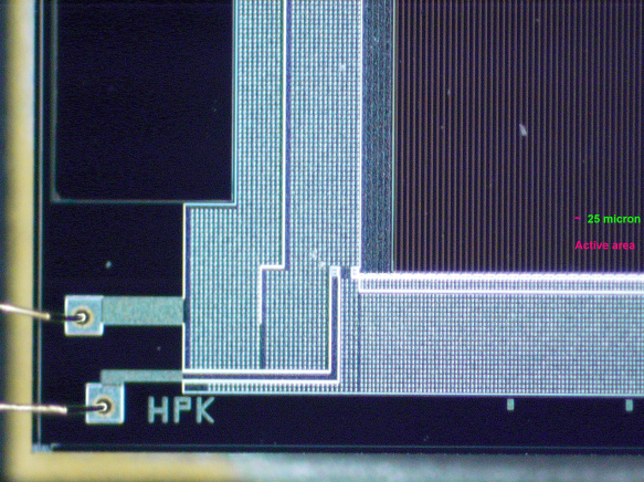
NMOS linear image sensor consisting of 1024 pixels of an N-type diffusion layer formed on a P-type silicon substrate.
Detection Method
The use of an indirect detection method, employing an X-ray scintillator (150 μm thick CsI (Cesium Iodide) coated on a fiber optic plate) to convert X-rays into visible light, extended the sensor lifetime to over a year.
| Parameter | Specification |
|---|---|
| Type | Current output type (with FOP) |
| Image Size | 25.6 × 2.5 mm |
| Number of Effective Pixels | 1024 × 1 pixels |
| Pixel Size | 25 × 2500 μm |
| Spectral Response Range | 360 – 1000 nm |
| Line Rate (max.) | 1950 lines/s |
| Cooling | Non-cooled |
| Window Material | Fiber optic plate |
| Package | Ceramic |
| Measurement Condition | Typ. Ta = 25 ℃, unless otherwise noted |
Source: Hamamatsu S3904-1024F
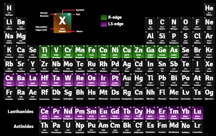
Absorption Edges Accessible at BL2.2
Elements marked with a + icon have standards available at BL2.2.