Beamline Layout and Specification
Beamline Layout and Specification
Beamline Layout and Specification
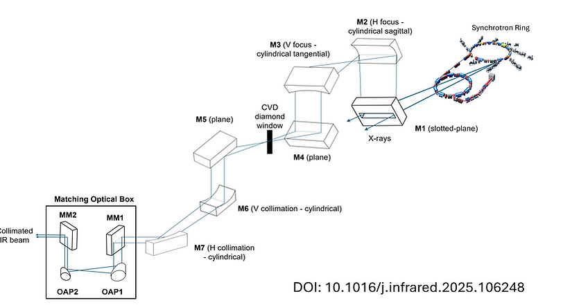
The beamline collects the infrared synchrotron emission from both edge radiation (ER) and bending magnet radiation (BM) of SPS-I where the synchrotron radiation is emitted from electrons traveling around the storage ring at nearly speed of light through a modified dipole chamber with opening-angle acceptance of 70H × 20V mrad2 after the bending magnet.
Behind the tunnel wall, the synchrotron light which covers a spectrum of electromagnetic waves from infrared to hard X-rays impacts on the first slotted flat mirror located at 45° angle in the horizontal plane laterally to the direction of synchrotron beam to reflect only the infrared beam including visible light. Then the second and third mirrors which are cylindrical shape are used to focus the beam horizontally and vertically, respectively. The fourth mirror delivers the beam through the wall tunnel. After that, the fifth – ninth mirrors positioned in a M5–M9 chamber are responsible to collimate and split the beam to accommodate up to 3 branches. Then a matching optical box is used to reduce the beam size before delivering the beam into the spectrometer.
Once the beam enters into the FT-IR spectrometer, Vertex 70 with assistance of the motorized matching box, and the Hyperion 2000 microscope coupling to the Vertex 70 focuses the IR beam in a wavenumber range of 4000 – 400 cm-1 to micro-scale beam size. The beam size at sample position will additionally be adjusted by an auto-aperture system in the Hyperion 2000 with respect to a size of the sample.