Beamline Operation

Personnel Safety
Interlock (PSI) System

Beamline
Manual
Safety Guidelines
for Operating BL2.2
IMPORTANT: Users must be aware of local restriction before using BL2.2
All users must strictly comply with the safety regulations and operational procedures of the Synchrotron Light Research
Institute (SLRI). Operation of Beamline 2.2 (BL2.2) is permitted only for trained and authorized personnel.
- Only users who have received authorization from the beamline scientist or safety officer are allowed to operate the
beamline. The user must sign on SOP form before expiremental performing at BL2.2. - Users must wear the provided OSL radiation badges (Optically Stimulated Luminescence dosimeters) at all times
within the experimental hall. - Entry to the experimental area is strictly prohibited during beam injection or operation.
- Any malfunction or abnormal condition related to radiation safety must be reported immediately to the beamline
staff. - Food and beverages are not permitted inside the beamline station.
- Users must maintain a clean and organized work area throughout the experiment.
- At the conclusion of beamtime, all personal materials and samples must be removed, and the beamline area must be
cleaned and restored to its original condition.
Personnel Safety
Interlock (PSI) System
PSI System protects workers from immediate radiation by preventing them from accessing beam enclosures and other locations where there is a risk of high radiation exposure. It consists of mechanical barriers and locks as well as electronic interlocks. The interlocks also serve to turn off the radiation source if any of the interlocked barriers entering the beam enclosures are broken.
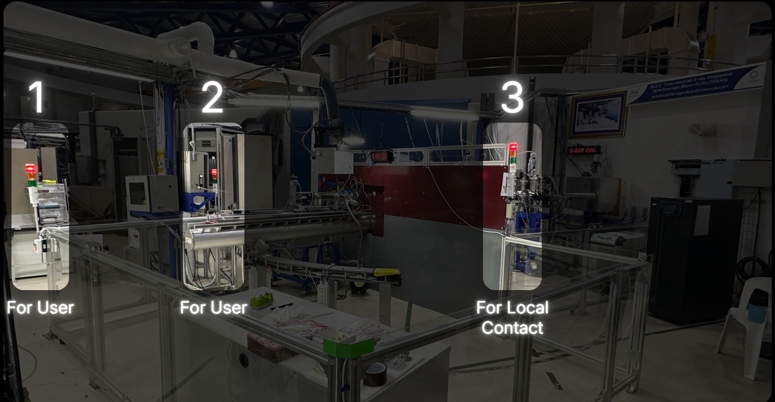
Closing the Hutch Door
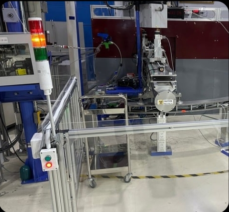
Press the red button, then slide the door closed. The tower light will change from green to yellow.*
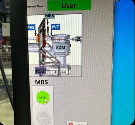
Open the shutters at positions MBS in the Interlock Beamline 2.2 program.
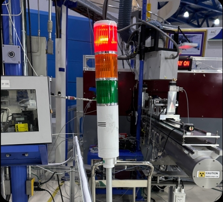
Once the door is opened, the tower light will change from yellow to red, indicating that the area is restricted.
*Note: If the light does not turn yellow, it indicates that the magnetic sensors on the door are not aligned.
Solution: Press the green button, slightly slide the door open, and repeat Step 1.
Opening the Hutch Door
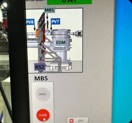
Close the MBS shutters in the Interlock Beamline 2.2 program.
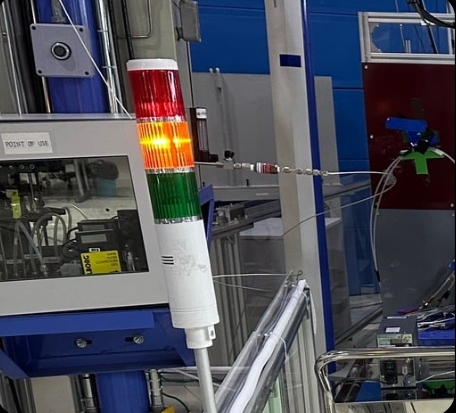
The tower light will change from red to yellow.
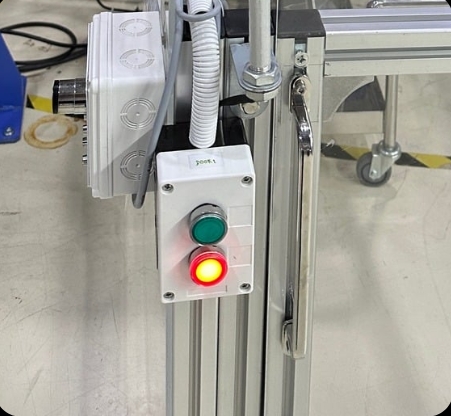
– Walk to the door control panel and press the green button to unlock the door.
– The tower light will change from yellow to green.
– Then slide the door open and enter the experimental area.
Beamline Manual
Sample Preparation
1 Pellet Preparation
Weigh the sample and Boron Nitride (BN) so that their combined weight falls within a range of 20 ± 2 mg. For example, if you weigh 3 mg of the sample, you should weight 15 mg of BN. Transfer both the sample and the BN into the grinding jar.
Recommendation: Place the grinding balls into the jar before pouring the powders in; this helps prevent the powder from dispersing or spilling out of the container.
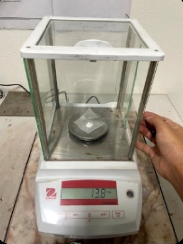
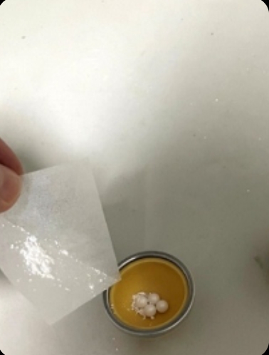
Mix the substances using a ball mill. Place the grinding jar between the clamping brackets and hand-tighten the locks at points A and B to ensure the jar remains secure. This prevents the grinding jar and balls from dislodging due to high-frequency vibration and extended operating time. Set the oscillation frequency to 25 Hz and the mixing time to 15 minutes.
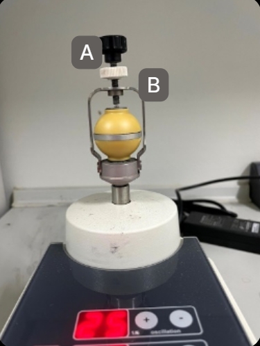
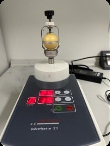
Once the time has elapsed, release the locks at points B and A. Use a stainless steel spatula to scrape off any material adhering to the surfaces of the grinding balls and the inner walls of the jar.
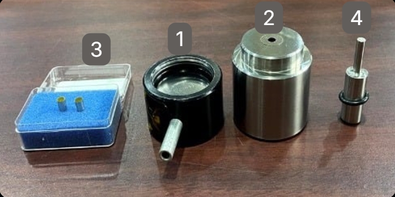
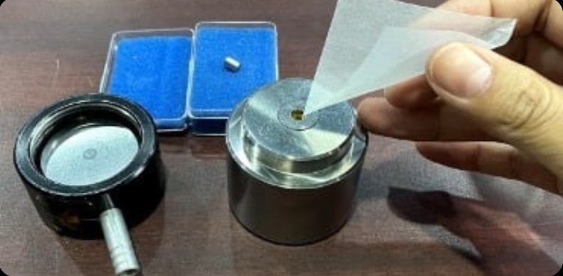
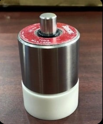
Pour the scraped powder into the 5 mm pellet die set. The assembly order of the die components and the sample is shown in the figure.
Recommendation: Pour the powder from the bottom of the die, as the distance to the pressing face is shorter than pouring from the top, which minimizes material loss.
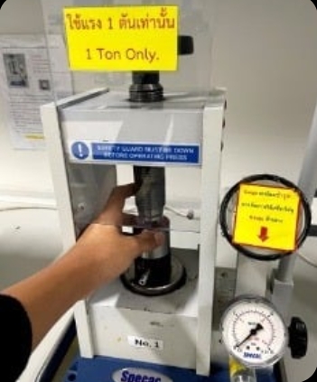
Place the die set into the pellet press to compress the powder. Apply a pressure of 1 Ton and maintain it for 45 seconds.
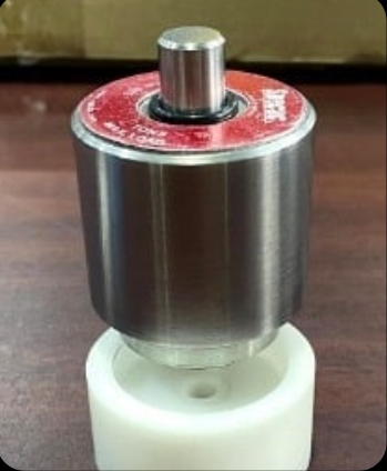
Remove the die set from the press and disassemble it.
Recommendation: Use a Teflon support base with a 5 mm center hole to hold the die while ejecting the sample. This reduces impact and prevents the pellet from popping out and getting lost. If the pellet remains stuck, place the Teflon base and die set back into the press and gently turn the top handle to apply steady pressure instead of using manual force. This method protects the die set from bending or damage caused by sudden impacts.
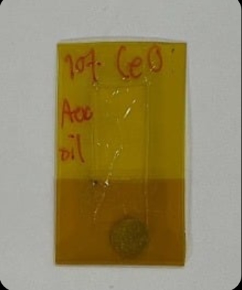
The resulting 5 mm pellet should be circular, with no chipped edges, cracks, or fractures.
Recommendation: Always verify the spectral quality of the prepared sample before installing it in the heating cell (as detailed in Section 5).
2 Sample Loading Procedure for the Heating Cell
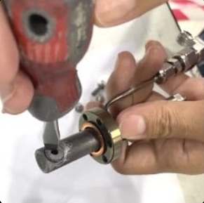
Place the experimental sample into the cell holder. Use a flat-head screwdriver to tighten and secure the sample. Verify that the sample is firmly held in place by gently shaking the cell holder back and forth.
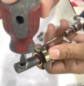
Insert the cell holder into the heating cell using a DN16 Gasket as a seal. Secure the cell holder to the heating cell using six M4 bolts. Ensure the sample is positioned exactly in the center of the heating cell; verify this by shining a light inside and inspecting it from the top view of the heating cell.
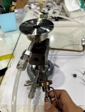
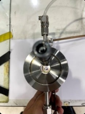
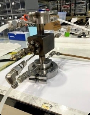
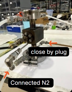
Once secured, perform a leak test on the heating cell using SNOOP leak detector in conjunction with nitrogen gas. If the six bolts are not sufficiently tightened, bubbles will appear during the test. Continue to tighten the bolts until no more bubbles are observed.
3 Installation of the Heating Cell to the Experimental Station
Heater Installation The heating cell features six slots for cartridge heaters. Insert the cartridge heaters firmly into the designated holes. Secure them by wrapping with cloth duct tape to prevent the heaters from slipping out of the cell.
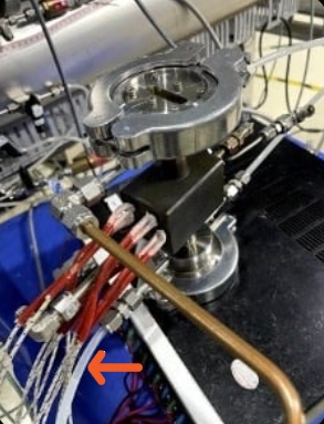
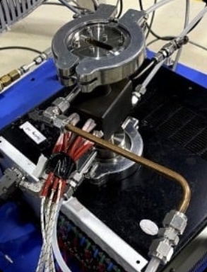
Mounting the Cell Proceed to install the heating cell at the experimental station. Use the cell cover to enclose the heating cell; this ensures stable heat distribution and allows the cell to reach high temperatures efficiently.
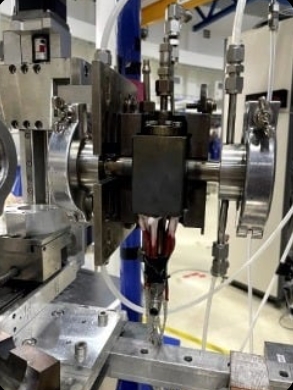
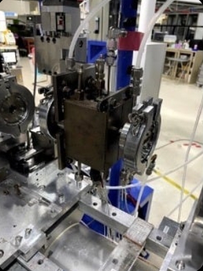
Connections and Cooling Insert the thermocouple into the heating cell. Connect the water inlet and outlet hoses to facilitate the cooling of the heating cell system.
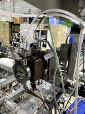
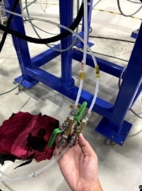
Note on Water Lines: Carefully observe the symbols for the water lines. Ensure the “Inlet” is connected to the inlet hose and the “Outlet” is connected to the outlet hose. Do not swap the connections.
4. System Setup Under Thermal Conditions
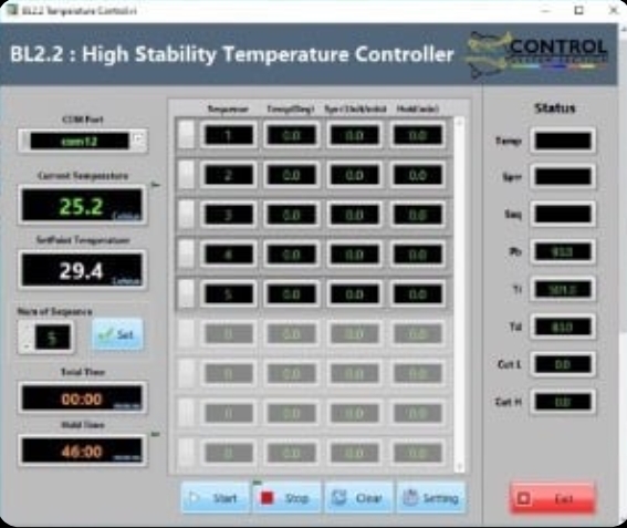
The system is operated via a control box and the Temperature Controller software. The control box manages
the interaction between the heaters and the thermocouple based on software commands. Users can define
the heating profile using the BL2.2 Temperature Controller software, which allows for the setting of target
temperatures, ramp rates, and dwell times for up to 999 steps.
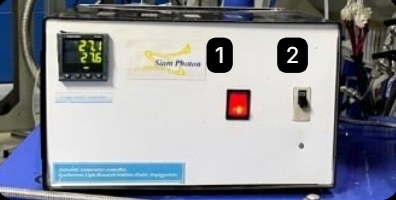
Turn on the main switch on the Temperature Control Box
(Switch No. 1).
Open the BL2.2 High Stability Temperature Controller software. The interface includes the following settings:
| Parameter | Description |
|---|---|
| Num of Sequence | Total number of steps in the experiment. |
| Sequence | The specific step number currently being edited. |
| Temp (Deg) | The target temperature for that step. |
| Sprr (Unit/min) | The heating rate (Set Point Rise Rate). |
| Hold (min) | The duration to maintain (soak) at that temperature. |
Once the experiment is complete, Click Exit at the bottom-right corner of the software. Turn off the main switch (No. 1). Pull down the safety breaker (No. 2).
Once all sequences are programmed, Click Start in the software. Lift the safety breaker (Cut-out) on the control box (No. 2) to begin the thermal cycle.
5. System Setup Under Gas Conditions
The station provides various gases, including H2 ,N2 ,Ar ,He ,O2 ,CO2 , and flammable gases. The flow rate is
regulated via a gas control box and dedicated Mass Flow Controller (MFC) software.
Safety Note: To prevent hazards during atmospheric experiments, gas leak sensors are installed at both the
gas cylinder storage area and the experimental station.
Turn on the gas flow control box using the main power switch. The switches on the control box function as follows:
Switch No. 1: Main power for the Gas Flow Control Box.
Switch No. 2: Controls the operation of Hydrogen (H2) and Oxygen (O2).
Switch No. 3: Controls the operation of Nitrogen (N2), Helium (He), and Argon (Ar).
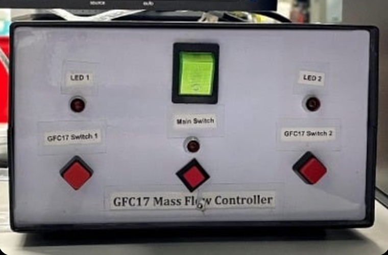
Open the Mass Flow Controls program. The software interface consists of the following parameters:
| Parameter | Description |
|---|---|
| C1 | Controls the flow rate for Hydrogen and Oxygen. |
| C2 | Controls the flow rate for Nitrogen, Helium, and Argon. |
| Flow Range | Sets the maximum range (0-100 ml/min). Note: For Hydrogen, the Flow Range must be limited to 0-25 ml/min only. |
| Select Actual Gases | Choose the specific gas being used for the experiment. |
| Input Range | Enter the desired flow rate value. |
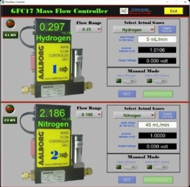
Note: Once the flow rate is set, the K-factor and Output Voltage values will be calculated and displayed automatically.
To Start:
After entering the desired flow rates, click SET to begin the gas flow.
To Shutdown:
Once the experiment is complete, click DISCONNECT.
A confirmation prompt will appear: “Are you sure you want to close GFC17 software?” Click YES.
Turn off the switches on the control box.
urn off the switches on the control box.
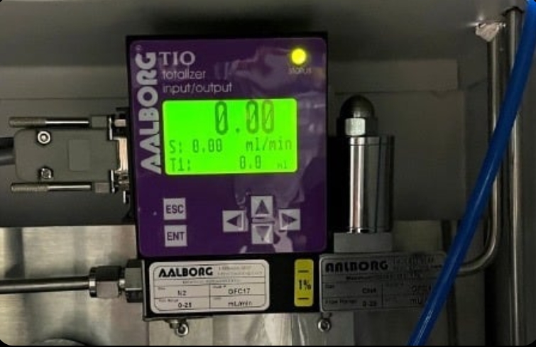
Methane flow is controlled manually directly on the flow control device:
Press ENT; the cursor will begin to blink on the digits.
Use the Up/Down arrow keys to increase or decrease the value.
Press ENT again to confirm the setting and begin the flow.
X-ray Absorption Spectrum
Recording
The station provides various gases, including H2 ,N2 ,Ar ,He ,O2 ,CO2 , and flammable gases. The flow rate is
regulated via a gas control box and dedicated Mass Flow Controller (MFC) software.
Safety Note: To prevent hazards during atmospheric experiments, gas leak sensors are installed at both the
gas cylinder storage area and the experimental station.
Open the C557-01APL program as shown in the figure.
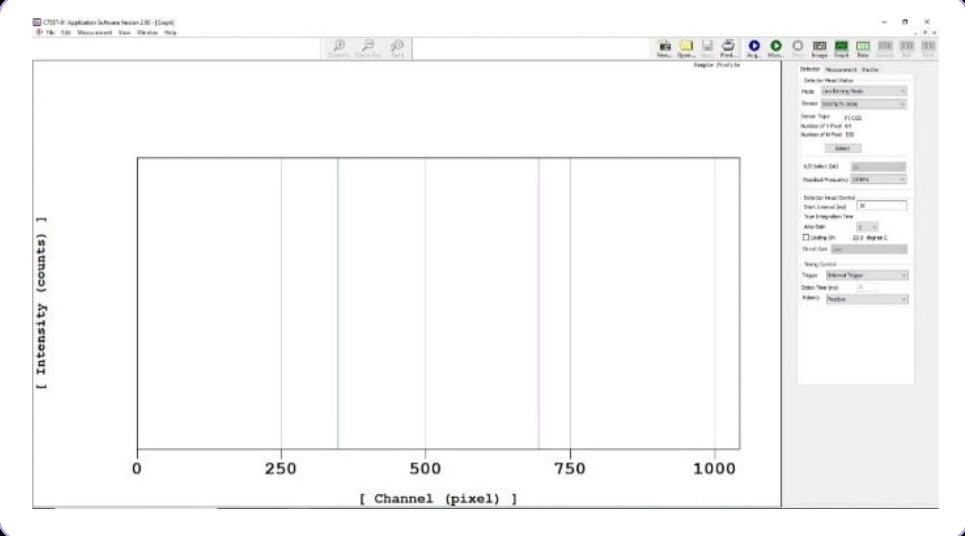
Detector Configuration On the Detector window, navigate to Detector Head Status and select s3903/048381-1024. Click Select, then click OK.
Acquisition Timing Define the data acquisition time in milliseconds by entering the value in the Start Interval (ms)field.
Measurement Settings On the Measurement window, configure the following settings:
- Set Measurement Control to Single shot
measurement. - Specify the number of spectra to be
measured in the Number of field. - Check the box for Averaging ON.
- Select Software Averaging to allow the
system to average multiple scans into a
single spectrum.
XAS Measurement Procedure (TRXAS Station) The X-ray absorption measurement requires separate recordings for I0 (incident intensity without sample) and I1 (transmitted intensity through the sample). Follow these steps:
Recording the I0 Spectrum
(Background)
In the Acquired Mode menu, select Dark Acquired and click Acq. The dark current spectrum will appear on the right side of the screen.
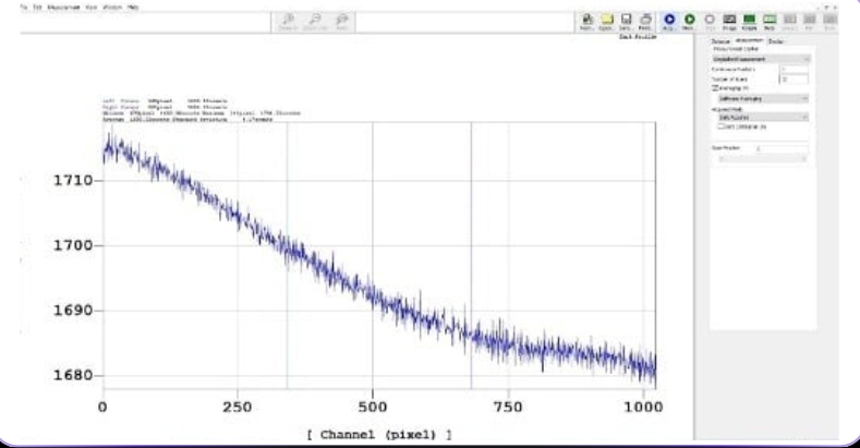
- Open the MBS (Main Beam Shutter) to
allow X-rays into the experimental
station. - Select Sample Acquired, ensure Dark
Calibration ON is checked, and click
Acq. - Once the measurement is complete,
Close the MBS. - Save the I0 spectrum: Go to File >
Save as, enter the filename, select the
file type as .txt, and click Save.
Recording the I1 Spectrum
(Sample)
Mount the sample onto the Holder as shown in the figure. Repeat the steps outlined in section 1
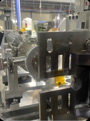
Note: It is recommended to perform a trial measurement before inserting the sample into the actual heating cell. This is to verify
that the sample thickness/concentration provides an appropriate Edge Jump for the experiment.
Once both I0 and I1 spectra are obtained, proceed to the data processing stage.
Data Analysis Tools
The Time-resolved X-ray Absorption Spectroscopy (TRXAS) technique at the Synchrotron Light Research Institute measures the X-ray absorption of specific elements. By utilizing an NMOS linear image sensor, the system can simultaneously record X-rays across all energy levels remaining after absorption. This capability significantly reduces the acquisition time per spectrum to less than 100 milliseconds.
A TRXAS dataset typically consists of two primary spectra:
I0
The measurement of the X-ray beam intensity without the sample.
I1
The measurement of the X-ray beam
intensity with the sample present.
These values are used to calculate the X-ray absorption, which is proportional to ln(I0/I1). Since the raw spectra are initially recorded in pixels, they must be calibrated into actual energy values.
Data Workflow
The data processing procedure is divided into two main stages:
Preprocessing Data
Converting raw data files into a format
compatible with the Athena software.
Athena Processing
Performing the pixel-to-energy
calibration.
Once these steps are completed, the resulting spectra are ready for detailed analysis and further scientific interpretation.
The Demeter software package (ATHENA) is free and open-source.
It can be downloaded from the official website. [click here]
Data Backup
Data Retrieval and Backup after Experiments at BL2.2
After completing your experiment at Beamline 2 (BL2.2.2), all data generated duning your session, ing raw
spectra, scan logs, and experimental parameters are stored automatically on the beamline local data serververver.
The following steps outline how users can retrieve and back up their data at the Synchrotron Light Research
Institute (SLRI).
Data Storage
During the experiment, all files (including scan data, configuration files, and experimental logs) are saved on the beamline control computer and mirrored to the local BL8 data server. Data are organized under folders named by Proposal ID or Experiment Date BL2.2 data are stored temporarily, typically up to 30 days after your beamtime, before being moved to archive storage or deleted to make space for new experiments.
Copying Data On-site
Users are strongly encouraged to copy their data to an external hard drive or USB device immediately after completing the experiment. Data can be copied directly from the beamline workstation or from the data server terminal provided in the experimental control area. The BL2.2 beamline scientist or local contact can help locate your folder and verify that all scans are saved correctly before you leave.
Requesting Data After Leaving SLRI
If you forget to back up your data during your visit or need additional copies, you can request remote access or a data transfer: Contact your local BL2.2 scientist or beamline staff by email.
Provide the following details:
- Proposal ID or beamtime number
- Date of your experiment
- Name of principal investigator (PI)
- Specific samples or scans required
Tip: Before leaving SLRI, confirm with your local contact that
- (1) all your scans are complete,
- (2) the data folder is backed up, and
- (3) the data copy on your external drive opens correctly.
Experimental Feedback
The Institute kindly requests all synchrotron users to submit the following
reports after completing their beamtime:
End of Experiment Feedback: Please complete the post-experiment
satisfaction evaluation through the BeamAppsystem after your experiment.
Experimental Report: Please submit a report summarizing the experimental
results within 14 days after the completion of the experiment via BeamApp.
(https://user.slri.or.th/beamapp/Account/login_Beamapp)